




Computer simulations always collaborate with the power electronics application development process, including the functional concept, component specification and selection, mechanical design, testing and validation, both under normal and fault conditions. Ideally, the development process refers to the familiar
Model V, shown in Figure 1, where design and implementation follow a top-down approach and verification follows a bottom-up approach. At each level, the developed application is verified with appropriate testing tools and procedures before being integrated into a larger system.
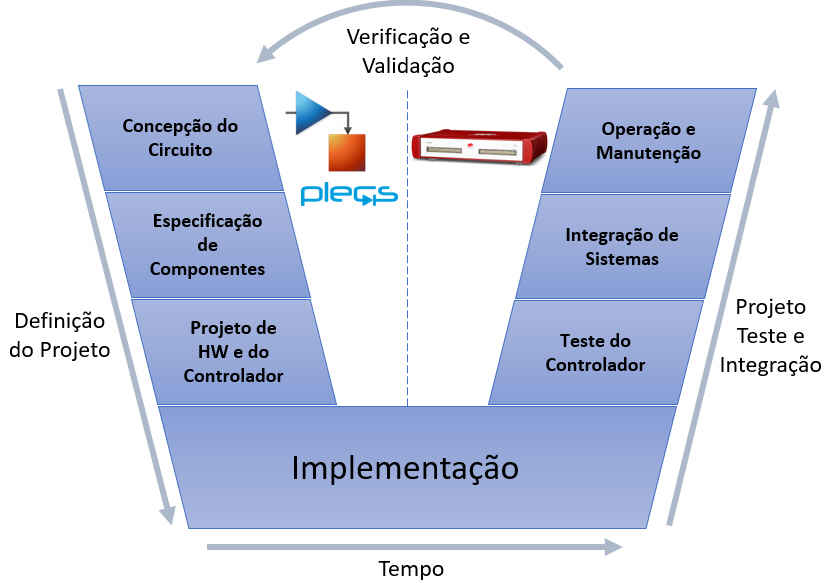 Figure 1: V-Model of the Power Electronics Development Process
For verification, it is important that the same adopted design specifications are used. Although design and verification tools can use models with different detail levels, it is important to ensure that the models produce comparable results. This article explains why a single model is not sufficient for all applications and how to ensure that multiple models deliver consistent results despite their different implementations and use cases.
In the first phase of a new project, the feasibility of a specific power circuit as well as a suitable control scheme can be quickly assessed with optimal circuit components and generic control blocks. During this conceptual phase, no manufacturer-specific information is required to model individual components (of a converter, for example). Instead, power semiconductors, such as IGBTs, MOSFETs, and diodes, are represented by simple on / off switches. The parasitic properties of passive components such as resistances and inductances may be disregarded unless they play a functional role in circuit operation.
Similarly, controls are represented by function block diagrams or state machines, regardless of their final implementation. These controls can later be performed as analog circuits, digital logic, microcontroller code, or PWM generator hardware. Simulation software used in the conceptual phase should provide generic models for all types of electrical components found in power electronics applications. Since power semiconductors are commonly used as switches, they should be modeled as ideal components to reduce the complexity of the simulation model. The designer must be able to freely connect arbitrary components and create their own custom components through subsystems, as we normally do in Plecs or Simulink softwares. At this stage the system model can grow in complexity and size. For fast transient simulations without significant integration errors, it is highly recommended to use a variable step calculation method so that the maximum integration error is not exceeded and switching times and other discontinuous events are accurately reached.
Based on the current and voltage requirements determined by the circuit design, suitable components with specific part numbers are selected and the mechanical layout is created. In this second phase, simulations help to predict thermal losses and associated temperatures. In a continuous workflow, the thermal model features a new layer placed over the electrical circuit. The thermal domain calculates the losses generated by the electrical circuit and models the heat transfer.
Switching and conduction losses can be simulated efficiently using a set of loss tables for each semiconductor. Switch loss tables provide the dissipated energy depending on the block voltage, conduction current, and junction temperature of the device. The tables for calculating conduction losses show the voltage drop as a function of the conduction current and the temperature of the device. At each step of the simulation, thermal losses are calculated and fed back into a thermal equivalent network comprising the semiconductor device, the heat sink and the chosen external cooling arrangement. The advantage of using loss tables rather than simulating voltage and current transients during switching is that switching becomes ideal and therefore high simulation speeds are maintained. The thermal domain calculation only adds some extra effort to the electrical simulation based on the ideal components. Power semiconductor loss tables used in modern simulators such as PLECs from Plexim are readily available on websites of various semiconductor manufacturers such as ABB, Infineon and Wolfspeed.
Based on the current and voltage requirements determined by the circuit design, suitable components with specific part numbers are selected and the mechanical layout is created. In this second phase, simulations help to predict thermal losses and associated temperatures. In a continuous workflow, the thermal model features a new layer placed over the electrical circuit. The thermal domain calculates the losses generated by the electrical circuit and models the heat transfer.
Mechanical design includes component placement, electrical layout, thermal design and integration into the housing. Because CAD programs and PCB layout software require many other parameters than those used for system simulations, the model tool chain is usually broken at this time. In mechanical design, the developer must adhere to the parameters used in the system simulation or modify them accordingly in the original data set. Using the spatial layout information of the mechanical design, the developer can determine the influence of parasitic inductances and EMI effects on an electrical simulation. This is only possible if detailed semiconductor models that accurately reproduce switching transients are used. As these models are computationally very heavy, only a few switching cycles are usually simulated.
In the classical approach, experienced software developers implement control code in a specific target MCU according to the specifications of the control specialists. Implementing embedded control code requires continuous testing. This can be simplified by compiling fragments of control code into a DLL intended for the host computer instead of the destination MCU. Most system simulation software can include DLLs so that the control code can be verified in a controlled system model.
A more modern approach to implementing controls in an MCU is to automatically generate specific C code from the functional block diagram. In addition to their offline implementation, each block must provide a method for generating C-code with real-time capability. The block diagram typically contains generic signal processing blocks as well as target input / output blocks for configuring on-chip peripherals such as ADCs and PWM generators. Especially for beginners, auto-coding greatly speeds development, because peripheral configuration through program code is a daunting task that requires in-depth MCU knowledge or extensive study of the manuals. With respect to model continuity, automatic coding has the advantage that the generated code always adheres to the block diagram definition. However, responsibility for efficient implementation of controls has now shifted from the software developer to the control engineer.
If the target MCU is not selected or the entire control panel with signal conditioning electronics is not yet available, the MCU may be temporarily replaced with a much more powerful real-time processing platform such as Typhoon Hil (available in TESLA/UFMG laboratory). This approach is known as Rapid Control Prototyping (RCP) and helps you quickly get a working configuration consisting of the power stage and the controller.
Handwritten or automatically generated codes can be checked in the block diagram definition in an offline simulation by replacing the block diagram with the compiled code. This type of verification is called software-in-the-loop loop (SIL) and allows for short response times as no MCUs need to be recorded. However, proper configuration of MCU peripherals cannot be verified with SIL, nor can timing problems, processor utilization, or resource corruption be detected on the destination MCU.
Testing not only the control code, but all control hardware, including MCU peripherals, typically requires that the actual power stage be connected to the controller. However, this is generally impractical because the power stage and its protection may not be fully developed prior to final commissioning, and certain failing operating conditions may damage the power stage.
To test the control hardware regardless of the power stage, the controller can be connected to a real-time simulator that mimics the behavior of the power stage. This approach is called Hardware-in-the-Loop (HIL) simulation because the actual control hardware is part of a closed loop simulation. Replacing the power stage with a real time simulation has the advantage that controller behavior can be extensively tested under a large number of normal conditions or under failures. Controller HIL testing has become very popular because the signal level connection provides a clearly defined interface between the controller and the power stage, and only a few modifications are required to replace the power stage with a real time simulator.
The challenge of HIL simulations of power electronics is the small time constants of electrical circuits. Only an additional short latency is acceptable, which is inevitably introduced by the real time simulator. The computational latency between PWM signal capture and simulated sensor signal delivery to the controller should be kept to a minimum, as the controller should still behave as if it were connected to the actual power stage. This requires not only dedicated real-time hardware, but also optimized converter models for fast and accurate execution in fixed step simulations.
Real-time simulations are always a race against time, as the calculation of each step must be completed within a discretization period. On a modern real-time platform, the minimum possible time is in the order of a few microseconds and may depend on model size. Even with specialized converter models, calculated entirely in FPGAs, the time interval can hardly be reduced below 0.5 µs.
The switching frequencies of today's converters are mainly between 10 and 100 kHz. If PWM signals were sampled only once per simulation step, the resolution of the captured duty cycle would be insufficient. To capture the duty cycle more accurately, PWM signals are generally sampled at much smaller intervals (about 10 ns) and averaged in the calculation step. Average PWM signals can only accurately represent semiconductor gate signals if they are applied to the appropriate converter models. These models are based on controllable voltage and current sources rather than the ideal switches (Figure 2). Additional logic is employed to model discontinuous driving mode and semiconductor suppression time.
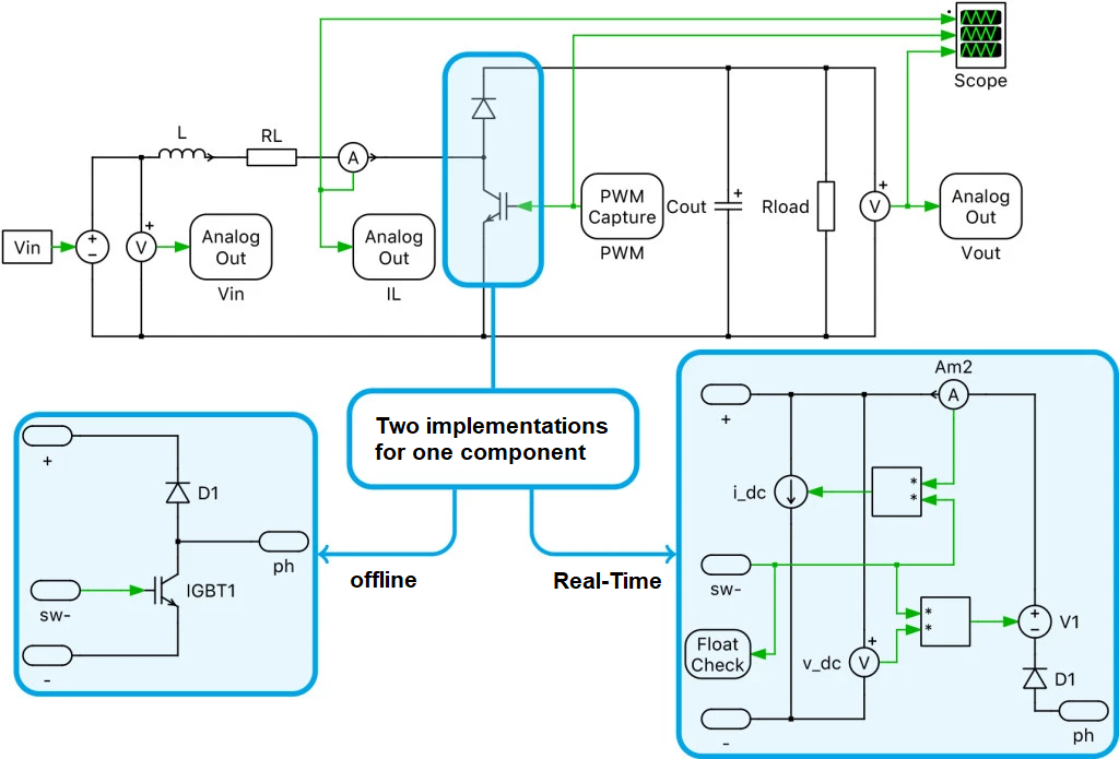
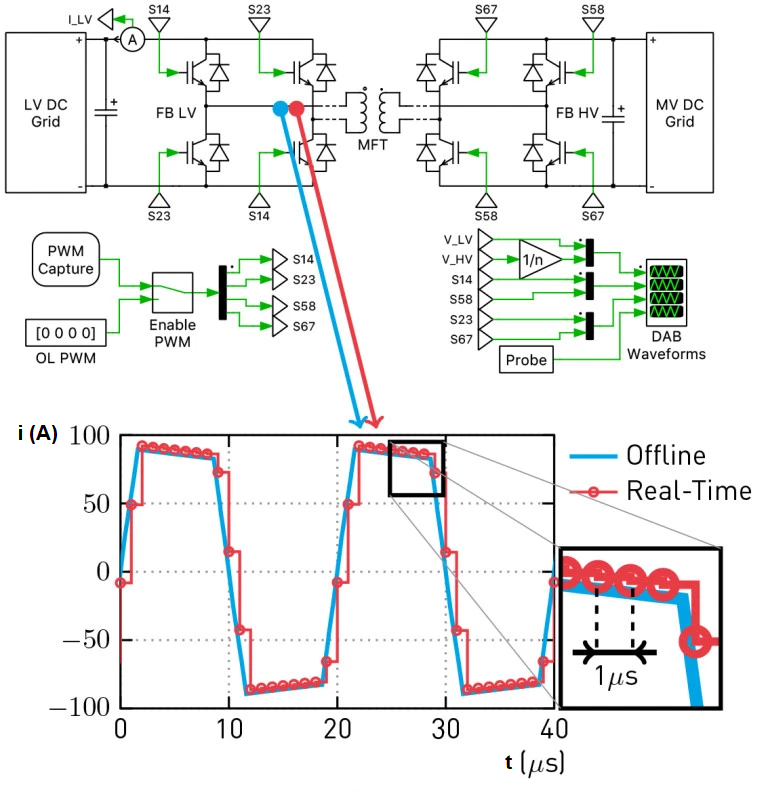 Figure 3: Real-time simulation results verification from offline simulation
Using the same model for all simulations throughout the development process, from design to verification, is an ideal goal that is difficult to achieve in practice. Different aspects, such as system or device behavior, may require various tools and simulation models with very different levels of detail. Getting a single model that resembles the whole system and using it as the only real source is therefore illusory.
Nevertheless, it is perfectly realistic to establish a development process in which all system parameters are stored in a central location and referenced by all models. This central location can be a comprehensive database or just a simple startup script. Certain parameters will only be used by some models to simulate selected aspects.
You are not authorised to post comments.